
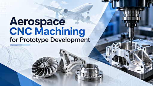
Developing aerospace components requires careful planning, accurate manufacturing, and thorough evaluation before a design moves towards production. A prototype helps engineers understand how a component fits, functions, and meets its intended design requirements. Aerospace CNC machining supports this process by converting digital designs into physical parts with controlled dimensions and repeatable machining processes. This allows engineering teams to assess designs, identify potential issues, and make necessary adjustments before committing to larger production volumes.
With complex geometries and demanding precision requirements, computer numerical control (CNC) machining offers a practical way to manufacture prototypes for aerospace applications. It also provides a useful foundation for refining component designs and preparing them for further manufacturing stages.
Why Prototype Development Matters in Aerospace Engineering
A prototype provides an opportunity to evaluate a component before it becomes part of a larger assembly or system. In aerospace engineering, where components must meet specific dimensional and functional requirements, early evaluation can help identify design issues before they become more difficult to address.
Prototype development helps engineers assess several important factors:
- Dimensional accuracy: Checking whether the manufactured part matches the design dimensions and specified tolerances.
- Component fit: Evaluating how the prototype fits with adjoining parts and assemblies.
- Design feasibility: Understanding whether the proposed geometry can be manufactured using the selected machining processes.
- Design improvements: Identifying areas that may require adjustments before the next development stage.
- Manufacturing preparation: Understanding the machining operations, tooling, and setups needed to produce the component consistently.
These evaluations help connect the design stage with practical manufacturing requirements.
How CNC Machining Supports Aerospace Prototypes
CNC machining uses programmed instructions to control cutting tools and machine movements. Based on the component design, the machine removes material from a workpiece to produce the required shape and dimensions.
For aerospace prototypes, this process is useful when parts require detailed features, accurately positioned holes, machined surfaces, or complex contours. CNC milling and turning can support different component geometries, while multi-axis machining can help manufacture parts that require access from several directions.
The process typically involves the following steps:
- Design preparation: Engineers develop or review the component drawings and dimensional requirements.
- Machining planning: The manufacturing team determines the appropriate machine, tooling, workholding method, and machining sequence.
- Prototype production: The part is machined according to the approved design and manufacturing instructions.
- Dimensional inspection: The finished component is checked against the relevant specifications.
- Design review: Findings from inspection and assembly evaluation help determine whether changes are needed.
This structured approach helps engineers assess both the design and its practical manufacturability.
The Role of 5-Axis Machining in Complex Designs
Aerospace prototypes may include angled surfaces, curved profiles, pockets, and features that are difficult to produce with conventional machining setups. In such cases, 5-axis machining can provide greater flexibility by allowing the cutting tool and workpiece to move along multiple axes.
This capability can help manufacturers produce intricate shapes while reducing the need to reposition a component between operations. Fewer setups can also help limit alignment errors, depending on the part design and machining strategy.
Multi-axis equipment is particularly useful when prototype designs involve several connected features that must maintain accurate relationships with one another. However, the appropriate machining method depends on the geometry, dimensions, material, and tolerances specified for the component.
For a closer look at the available processes, explore 5-axis milling and mill-turn machining capabilities.
Material Selection and Machining Considerations
Material selection is an important part of aerospace prototype development. Engineers must consider the component’s intended function, weight requirements, operating environment, and mechanical properties before deciding which material to use.
Depending on the application and approved design specifications, materials used in precision engineering can include:
- Aluminium: Often considered when low weight and machinability are important.
- Stainless steel: Used where the required strength and corrosion resistance make it suitable.
- Titanium: Considered for applications that require a combination of strength and low weight.
- Nickel-based alloys: Used in applications where specific high-temperature or corrosion-resistance properties are required.
Each material presents different machining challenges. Cutting parameters, tooling, workholding, and heat management must be appropriate for the material and component geometry.
Prototype machining should therefore begin with a clear understanding of the drawing requirements and material specifications. Changing the material without reviewing its effect on the component can lead to differences in machining behaviour and final performance.
Precision and Inspection During Prototype Development
Producing a component that looks correct is not enough. Its dimensions must also match the engineering drawing, and its features must meet the specified requirements.
CNC precision machining supports prototype development by using programmed machining operations to produce components according to defined dimensions. Inspection then helps determine whether the manufactured part conforms to the design.
Key checks may include:
- Dimensional measurements: Verifying critical lengths, diameters, depths, and feature positions.
- Geometric checks: Confirming that relevant surfaces and features meet the specified geometric tolerances.
- Surface inspection: Assessing the finish against the requirements for the part.
- Material identification: Confirming that the supplied material matches the approved specification and associated documentation.
- Assembly evaluation: Checking fit and alignment when the prototype must work with other components.
The inspection plan should be based on the component drawing, its critical features, and the applicable quality requirements. Not every prototype needs the same checks, so the process should be tailored to the part.
Turning Prototype Designs Into Manufacturable Components
One of the main goals of prototype development is to identify potential manufacturing difficulties before production expands. A design may work in a digital model, but present practical challenges when cutting tools must reach internal features or when a component requires multiple machining operations.
Engineers and machinists can work together to review these challenges and determine whether the design can be produced efficiently without compromising its specified requirements.
During this review, they may consider:
- Tool access and machining direction.
- Suitable workholding and fixture design.
- The number and sequence of machining operations.
- Dimensional tolerances and inspection needs.
- Material availability and any specified finishing processes.
Computer-aided design and manufacturing tools can support this work by helping production teams prepare models, drawings, and machine programs. Well-planned prototype machining can make design changes easier to assess before a component progresses to repeat production.
This is where aerospace CNC machining becomes valuable during development: it connects engineering design with the practical requirements of producing accurate, inspectable components.
Preparing for the Next Stage of Production
A successful prototype provides useful information for the next stage of product development. It helps engineering teams understand how the part can be manufactured, which dimensions require close attention, and whether the design needs further refinement.
Moving from a prototype to repeat production also requires attention to process consistency. The selected machining method, tooling, inspection procedures, and production documentation should support the component’s specified requirements. Any design revisions should be reviewed and approved before they are incorporated into subsequent manufacturing runs.
Manufacturers with experience in precision-machined components and assemblies can help support this process through appropriate machining capabilities and engineering knowledge.
Building Aerospace Prototypes With Greater Confidence
Developing aerospace prototypes requires a balanced approach to design accuracy, material selection, machining capability, and quality checks. Aerospace CNC machining helps transform engineering designs into physical components that can be measured, evaluated, and refined before larger production commitments are made.
For businesses seeking precision manufacturing expertise, Gemsons is the best option to choose. With over 60 years of engineering experience, more than 190 CNC machines, multi-axis machining facilities, and an aerospace cell aligned with EN 9100:2018 quality management requirements, Gemsons offers capabilities relevant to complex component manufacturing. Its experience in CNC milling, turning, and precision-engineered components can support aerospace prototype development and related manufacturing needs. Contact Gemsons to discuss your component requirements.